Extending the sidelight / speakerlight cable
The information is for a sidelight.
The speakerlight cable has additional wires which go to pins 10 and 11. These wires may be thicker than the rest (I need to check as I’ve forgotten). Although it’s not likely that anybody would want to extend the speakerlight cable, the information below can also be used for the speakerlights. Because the wires to pins 10 and 11 in the extension cable will be thinner, it’s possible that there might be a slight loss of audio quality or volume.
Unlike the fans and rumbler, the sidelight cables carry signals as well as the voltage supply. Extending the cable may cause problems, especially if the cable is too long.
The sidelight has a 15-
If you are buying an extension cable, you need to get one with a M-
Monitor extension leads are readily available, but cannot be used because of the
missing pin. Extension cables and M-
Often these cables contain several wires with individual screens. As long as the screens are insulated from each other and do not touch each other in the cable, then this should not be a problem. Another thing to check is that the pins aren’t short circuited together inside the plug / socket. This may sometimes occur when the shields are connected to a common ground. This is more likely in standard monitor cables rather than the fully wired type, but it is best to check before you use the cable and so avoid any risk of damage to the sidelight or wallwasher. Use the grid test below.
If you currently have a suitable M-
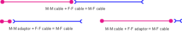
Fig. SE1: Converting a M-
How long can the cable be?
Because the cable doesn’t contain signals, then the length of a cable might not be too important. However, the longer the cable, the more susceptible it is to voltage drop, although the drop is minor. I have connected various cables together to make up a 19m extension cable for testing and the light worked fine. If anybody else has successfully used a longer cable, then please let me know.
Where can I buy the cable or parts?
See the Components page for details
Make up your own extension cable
Personally, I wouldn’t bother to make up a cable. The cost of the parts and the cable would probably cost more than a bought cable, plus it will be time consuming. However there might be a reason you want to make your own, so I’ve provided the following information:
The 15-
Just connect pin 1 in the plug to hole 1 in the socket, pin 2 in the plug to hole 2 in the socket, and so on. Remember that the plug / socket will be wired in a mirror image. You will also need to connect the shield of the cable to the shell of the plug / socket. This will be difficult to do because there is normally no connection on the shell for this.
Make up your own adaptor to use an existing suitable monitor extension cable
If you have some monitor extension cables with the pin / hole missing and you have
tested them to check that they are suitable, one way you could use them is to make
up an adaptor to fit between the socket on the wallwasher and the plug on the light.
This involves making up a short cable connector with a fifteen pin socket on one
end and a fifteen pin plug on the other -
There are two ways to do this:
One way is using a chassis plug and chassis socket fitted into a 9 way D-
The other way is to make up a mini extension lead, with a plug at one end and a socket at the other, wired in the same way.
There is one simpler option if you’re good with a soldering iron and have a steady
hand. You could use a monitor port saver. This is M-
Fig. SE3: shows a modified port saver with pins 12 (top row, 2nd from the right) and 9 (middle row, second from the left) shorted together. It’s very hard to actually see anything, because most of the wire is covered by the insulation (the black blob). The short was made by taking one very thin strand of wire and threading it through the hole in a piece of insulation that had had the bundle of wires removed. Each end of the wire was then twisted round the pin it was connecting to and soldered quickly with a very small soldering bit. It was very time consuming getting it right. A thicker piece of wire would have been easier to bend and hold in place, but it might have been too too thick and cause problems when fitting the plug in the socket.
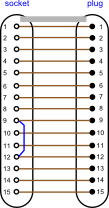
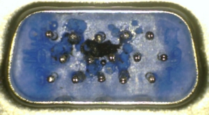
Fig. SE2: Monitor cable adaptor Fig. SE3: Monitor port saver with short
Warning
You have to be careful if using an existing monitor extension cable
One thing that does concern me is that various connections on the monitor plug are for ground. If these connections have been shorted together within the plug, this could lead to a short circuit of some of the connections between the sidelight and the wallwasher when the extension cable is connected. Likewise, if the cable uses individually screened wires with each screen connected to a separate pin, a short circuit between the shields is likely to occur within the cable, and this would give the same effect as two or more pins being shorted together. Test any cable using the grid test
Testing a cable -
Also see the general testing information on the Extending the cables tab.
You will need to check all possible connections between pins, holes, and shell. With
a 15 pin cable, this forms a 16 x 16 grid -
Start with hole 1 and pin 1, then hole 1 and pin 2 and so on. After you’ve tried hole 1 and pin 15, then try pin 1 with the socket shell. Repeat this process with hole 2 and pin 1 and so on until you’ve tested hole 15 and the socket shell. Finally, try the plug shell with pin 1 and so on until you finish with plug shell and socket shell. The resulting grid should be a diagonal line as shown. If you have any other squares highlighted on the grid, then the cable isn’t suitable. If the grid doesn’t look right or you realise the something isn’t right as you’re going through the test, try that connection again. It’s easy to short the probe / wire against adjacent pins / the shell when doing the test.
The test all sounds very complicated, but in fact it’s quite simple, albeit a bit boring. However it’s worth doing rather than using an untested cable and risking damage. A shortcut that I use is to slowly move the probe / wire across the row of pins, being careful not to short across adjacent pins. This is an ideal method when using a tester that makes a noise. As the probe touches the pin that’s connected to the socket where the other wire is, then you will get a noise. Double check that it is only the one pin that’s affected, by moving the probe back and forward to the adjacent pins. Doing the test like this means that you have tested the whole row of pins in a matter of seconds.
Remember that the plug and socket will be a mirror image of each other. If you have
the plug and socket both facing you, the same way up, then pin 1 will be on the left
on the plug and hole 1 will be on the right -
The correct result of the grid test is shown below. If any other square is highlighted or blank, then the cable is not suitable.
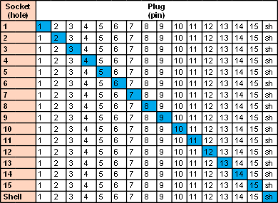
Fig. SE4: Grid test -
Replacing the plug
If you have to replace the plug, identify what wires go to what pins on the plug.
If the wires inside the cable are the same colour as those shown on the pin-
Instead of replacing the plug, you could replace the plug and cable as detailed below.
Replacing the cable
The simplest, and probably cheapest, way to replace the cable is to get a suitable
F-
You will need to identify the wires and make sure you know what holes they go to in the plug. I haven’t taken one of the extension cables apart, so I’m not sure how they’re wired up. It may be that a wire has a screen over it and that screen is counted as one of the wires.
Connecting the other end of the cable to the PCB connector plug, J5, will be a bit difficult unless you have replacement crimp connectors to fit in the connector holes. As long as that part of the existing cable that is within the sidelight base isn’t damaged, then you could cut the wires from the J5 connector, leaving about 180mm of wires still connected to J5. You could then just join the wires from the new cable to these wires using a suitable form of connector. Make sure that the wires going to J5 2/3 are twisted together, J5 4/5 are twisted together, J5 6/7 are twisted together, J5 8/9 are twisted together. One of each of these wires is a ground connection and helps reduce interference. You will need to join the wires together that come from the sidelight plug holes 9 and 12. Normally, this would be done inside the plug, but the plug on the new cable will be sealed. Instead, they can just be joined together with the wire that goes to J5 hole 9. Only connect the wires from plug holes 9 and 12 together. Do not connect to any of the other GND wires.
Another option, or if the wires near J5 connector are faulty, or J5 connector is faulty, is to use another connector to fit onto the PCB pins of J5. Unless you’re lucky, you are unlikely to have an exact replacement connector. However, the pin spacing is standard 2.54mm (0.1 inch), and other connectors can be used if you’re careful. One method is to use the connectors that are used to connect the PC on/off switch, indicator light, external USB sockets etc. to the PC motherboard. This is what I do when I need to make different connections to the PCB. I use solderless LED holders which have a double socket at one end and a red and black cable at the other. I connect these to pins 2/3, 4/5, 6/7, 8/9 and a single socket for pin 1. The wires from these are then connected to the light cable as before. If you are using this method, it is important that you don’t get the wires mixed up or connect the sockets to the wrong pins.
Testing the cable
Whatever method you use, once you have connected the new cable up, you need to test
it to make sure that the same hole on the sidelight plug goes to the same hole on
the J5 connector -
Finally, after checking once again that all connections are correct, plug in the sidelight and check that the light is working correctly.
Cable makeup
The Cabling4less fully wired 15 pin cables are made up of an outer braid sheath,
an inner foil sheath and have a bare copper wire running through the bundle of wires.
All three are connected to the plug / socket shell only, not to any pins. The bundle
of wires contains nine individual wires and three, thicker wires. These wires are
individually screened and insulated. The screen from each wire is treated as an individual
wire and does to its own connection, just like the other wires. Details of the wire
colours and pin / hole connections are shown below. Always confirm what colour goes
to what pin / hole as it’s possible that this may change, even with the same cables
from the same supplier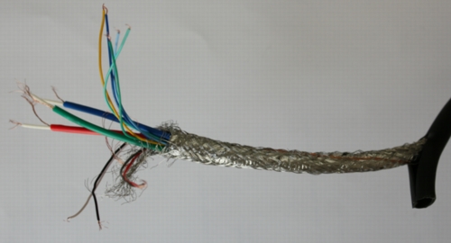
1 Thick red
2 Thick green
3 Thick blue
4 Black
5 Red
6 Thick red screen
7 Thick green screen
8 Thick blue screen
9 Yellow
10 Dark green
11 Light green
12 Dark blue
13 Light blue
14 Grey
15 White
Screen + inner copper wire
-
Fig. SE5: Cabling4less all wires connected cable
If you are soldering these wires to a plug / socket or connecting them to other wires,
make sure that the screens on the thick wires are not touching any other contact.
You could perhaps heat-
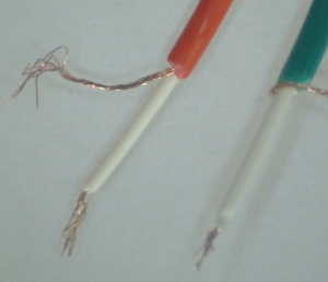
Fig. SE6: Thick wire with internal shield
The shield is treated exactly the same as any of the other wires in the cable and is connected to one pin. The shield is made up of several fine wires.Care must be taken to ensure the shield doesn’t short to any other pin.